 Mini Review
The Impact of Motive Nozzle Spacing and Surface Roughness on The Performance of Axial Water- Oil Jet Pumps in an Egyptian Offshore Oil Field: An Experimental and Computational Investigation
AAA Sheha1,2*, KA Ibrahim2, HA Abdalla2, Samy M El Behery2 and IM Sakr2
1Mechanical Section Head, Petro Gulf Misr Petroleum Company, 10, St. 250 Sarayat El-Maadi, Cairo, Egypt
2Mechanical Power Engineering Department, Faculty of Engineering, Menoufia University, Shebin El-Kom Egypt
AAA Sheha, Mechanical Section Head, Petro Gulf Misr Petroleum Company, 10, St. 250 Sarayat El-Maadi, Cairo, Egypt
Received Date:November 06, 2023; Published Date:December 19, 2023
Abstract
The petroleum fields suffer from the low efficiency of the jet pump because a smooth inner wall is often necessary for the jet pump during the mixing of the primary and induced fluids and the transfer of momentum from the primary fluid to the induced fluid. When fluids move over extremely uneven surfaces, energy is also lost due to friction loss that occurs along the inner pump walls. So, surface roughness has a big effect on the efficiency of jet pump. Moreover, motive nozzle spacing is considered important factor for controlling motive energy loss that results in low efficiency. Experimental field data and computational studies in the present work are focused on a water-oil jet pump used to extract crude oil from petroleum sites. Well productivity is demonstrated to be significantly influenced by the effect of pump roughness. Furthermore, because excessive roughness can lower a pump’s productivity by 23-27%, it highlights the necessity of optimizing the pump’s roughness. The best efficiency and its flow rate ratio gradually decrease with increasing pump’s surface roughness. The optimal motive nozzle relative position is determined to be 1.
Keywords:Water-Oil Jet Pump; Surface-Roughness; Performance; Experimental; Computational
Introduction and Literature Survey
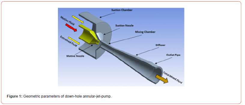
When the reservoir’s energy is insufficient to let a well to flow or when the required rate of production surpasses the reservoir’s capacity, an artificial lift must be built in the well to boost the reservoir’s natural energy in order to bring the requisite fluid to the surface [1]. A jet pump is considered one method of artificial lift that is utilized when the bottom hole flowing pressure is smaller than the tubing pressure difference caused by a fluid with a specific flowing gradient. Due to its straightforward design and construction, the jet pump performs effectively in a range of industrial environments. Jet pump inner wall surface roughness affects oil output because it affects production rate and raises operating expenses when surface roughness is high. An annular nozzle, a suction chamber, a suction nozzle, a mixing chamber, a diffuser, and an exit pipe are the parts of the down-hole annular-jet pump shown in Figure 1. As the fluid passes through the annular nozzle, it changes from highpressure motive fluid to high-kinetic energy fluid. When the lowpressure (low-velocity) entrained fluid comes into contact with the motive fluid, it is dragged to greater pressure. A two-phase mixture is produced at the diffuser’s entrance as a result of the two fluids mixing together in the mixing chamber.

The diffuser increases the outlet pressure by transforming the combined fluids’ kinetic energy into pressure energy [2]. Data on flow description was supplied for annular jet pumps and associated components by [3,4]. The inner walls of the jet pump have a considerable surface roughness, which results in significant friction loss and low efficiency since a smooth surface is required when the two fluids are going through the pump. The surface roughness requires to be optimized for each usage of the jet pump in order to achieve the maximum pump efficiency. Therefore, increasing the surface roughness of the inner pump wall has an impact on the performance of jet pumps because it generates friction loss. In order to obtain a fundamental understanding of how surface roughness affects jet pump performance, experimental and computational studies are conducted for various surface roughness values on a water-oil jet pump used in petroleum oil fields. The validity of the flow rate ratio is demonstrated by comparing 3D computational work with experimental field data obtained from PetroGulf Misr Petroleum company. Then, it is investigated how each roughness affects the frictional resistance factor along the pump inner wall.
The level of surface smoothness is crucial for an efficient jet pump operation. Petroleum companies have motivated manufacturers and researchers to concentrate on improving jet pump efficiency to decrease the quantity of consumed motive power. Over the past few years, a growing variety of energy-saving solutions have been proposed [5,6].
Yamazaki et al. [7] conducted an experimental investigation to examine the impact of mixing chamber surface roughness and the position of roughness on the efficiency of a water jet pump. Their findings showed that roughness has a bigger impact on the efficiency of the pump. They found that as the relative roughness increases, the mass flow rate ratio and the optimum efficiency ratio both fall linearly. Li et al. [8] experimentally studied the impact of the internal surface roughness of the nozzle on the patterns of cavitation erosion jets. They came to the conclusion that the high rough surface caused high energy loss and resulted the jets to split.
Guelich et al. [9] experimentally and analytically studied the effect of wall roughness on the pump efficiency. Their study revealed that the hydraulic loss depended on the inner wall roughness. Aldas and Yapici [10] utilized CFD numerical study to determine the effect of absolute and relative roughness on efficiency of jet pump. It was discovered that efficiency greatly increased up to a certain point under specified absolute roughness. Li and Wang [11] conducted numerical study to investigate the effect of surface roughness on the performance of an axial pump. They came to the conclusion that when surface roughness increases, pump efficiency declines. Sheha [12] list the important considerations that must be taken when designing a jet pump. Zhu et al. [13] Carried out numerical study to model how the performance of axial flow pump would be affected by the roughness of pump inner walls. They came to the conclusion that reducing the pump’s surface roughness would greatly boost head and efficiency. Moreover, changes in inner wall roughness were more likely to occur with the axial flow pump due to its efficiency. Pan et al. [14] carried out simulation study to determine the performance of the axial flow pump under the influence of various rough walls. They found that the presence of wall roughness caused a reduction in the pump’s head and efficiency, with the efficiency reduction being the most pronounced. Echouchene et al. [15] Carried out numerical study to investigate the effect of wall roughness on the cavitation of the flow. Their findings indicates that the length of cavitation is clearly influenced by pump wall roughness. Sheha et al. [16] carried out numerical and experimental study to determine the optimum value for nozzle relative position of the axial water-jet-pump. They concluded that the optimum value for nozzle relative position is found to be (1).
As a result, the present work focused on roughness effect on the performance of the water-oil jet pump used to extract crude oil from petroleum sites. In addition to specifying the optimum relative position of motive nozzle. The goal of the current study is accomplished by experimental and computational work. Experimental work is carried out in one of the Egyptian offshore oil fields via using the field data. Computational work is carried out using ANSYS software, and is validated with a previous computational and experimental, in addition to the validation with the field data.
Research Methodology
The jet pump is the most frequently employed artificial lift technology in Egypt and around the world, so a thorough study of the surface roughness effect and motive nozzle relative position on the performance of jet pumps is required to understand how surface roughness and the wrong motive nozzle relative position affect the jet pump performance, decreasingly. This goal is mostly focused on the right selection of the best material and the best nozzle relative position to optimize down-hole jet pump production. The CFD commercial code (ANSYS® FLUENT, Release 17.0) was utilized in a recent study to investigate the surface roughness effect on the efficiency of water-oil jet pump. In addition to investigating the effect of motive nozzle spacing for controlling motive energy loss that result in low efficiency.
The Numerical Model
A finite volume discretization was used in the calculations using an academic edition of the ANSYS Fluent R 17.0 CFD code. The numerical simulation is conducted using a three-dimensional steady-state water flow via the pump. The purpose of the jet pump benchmark testing was to investigate how axial water-oil jet pump performance is affected by geometrical and operational factors. Additionally, simulate how the pump’s flow behaves with these various geometrical and operational settings. The SST k-ω turbulence model was suggested for the current investigation by earlier research [12]. A water jet pump’s flow is a mixture of flows for which there is intricate physics at play.
Because of the rotational symmetry, just half of the axial jet pump was used as the computational domain, rather than the entire pump. For the fluid zone, the rotational-symmetry boundary condition was used. ANSYS Meshing was used to generate hybrid meshes. It took about 316698 cells for the pump to generate meshindependent solutions. To increase the accuracy of the boundary layer simulation, inflated mesh was employed in the vicinity of the wall boundaries. Prismatic inflation cell layers were first created independently in the near-wall region in sets of two to eight during the inflated meshing process. A first layer height of 45×10^(-3) m and a growth rate of 1.2 were applied to each layer. A 3D doubleprecision pressure-based solver type was used in order to improve the turbulent flow field’s resolution. The pressure inlet boundary condition in this numerical simulation study is set to the total pressures of the motive flow. For each run, the turbulence strength and intermittency were utilized to define the turbulence boundary conditions. The intermittency and turbulence intensity at the jet pump’s inlets and outlet are adjusted to 1 and 5%, respectively, in the SST k-ω model calculations.
The Field Information of PetroGulf Misr Company
The concession areas are located in a shallow water archipelago in the southwest inlet of the Gulf of Suez, roughly 80 kilometers northwest of Hurghada City. The firm operates an offshore oil field. Tawila West Field and Geisum Field are included in the concession areas. The company was originally known as Geisum and was founded as a joint venture between EGPC and Conoco. The company successfully drilled four wells in South Field during the partnership’s years of 1985–1987. After Ganope, Pico Gos Petroleum firm limited, and Kufpec (Egypt) limited established a joint partnership firm, the Geisum Oil Company was renamed PetroGulf Misr Company in 2008.
The Description and Input Parameters of Present Study Well “GA-1A”
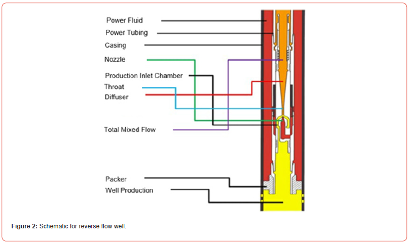
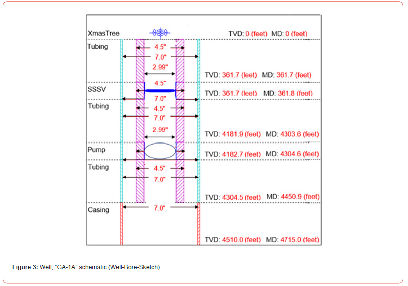
The purpose of drilling well “GA-1A” was to extract oil from the company’s south field located in Egypt near the southwest entrance of the Gulf of Suez. This was done 37 years ago. The drilling was finished down to 4715 feet. With a GOR of 180 scf/stb and 97% water cut via a 4.50-inch (2.99-inch ID) tubing put in a 7-inch casing with a pump installation, the well produced 22.1 API oil. Gas has a specific gravity of 0.809 and water has a specific gravity of 1.21. The reservoir is 140°F, while the wellhead is 123°F. Figure. 2 shows reverse flow technique configuration. More details can be obtained from [17] and [18].
The schematic of well “GA-1A” (Well-bore-Sketch), which produces from the basement layer, is depicted in Figure 3. The top basement stratum is at ORKB MD, 4704 feet away.
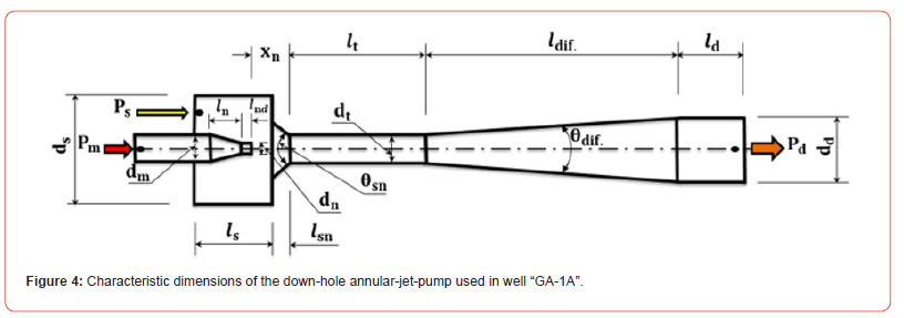
The down-hole jet pump is designed and fabricated from Tungsten Carbide with smooth inner surface (K_s=20 × 10^(-6) mm). Figure 4 shows the characteristic dimensions of the downhole annular-jet-pump that is used for producing oil from well “GA- 1A”. The actual pump dimensions are mentioned in Table 1.
Table 1:Jet pump dimensions used in well «GA-1A».


Conclusion
This study examined how the relative location of the motive
nozzle and the surface roughness of the pump affected the
efficiency of the axial water-oil jet pump, which in turn affected
oil production. Using experimental field data from real oil well
and numerical techniques, the optimization study produced the
following findings:
a) One important aspect affecting the friction term in the
pressure losses is the roughness of the pump.
b) The findings of this investigation show that the pump’s
ability to produce liquid reduces with increasing roughness.
Liquid production is reduced by 23.126% when the pump’s
roughness is increased to 0.01 inches (compared to its value at
0.0004-inch roughness). This suggests that in order to increase
the pump’s capacity to produce liquid, roughness is a crucial
component that needs to be taken into account.
c) The axial water-oil pump’s roughness is extremely
important and should be taken into account as it might reduce
the pump’s productivity by up to 23-27%.
d) Using values ranging from 0 to 3, the optimization study
is conducted to determine the optimum relative location of the
motive nozzle. The ideal value is found to be 1.
e) Finally, in order to save time and money spent in the actual
oil field, the physics of flow within axial water-oil jet pumps can
be analyzed and the optimization can be easily performed by
using the CFD, 3D technique to predict one or more geometrical
and operational parameters on the pump’s efficiency.
Acknowledgement
None.
Conflict of Interest
There is no Conflict of interest.
References
- API E&P Dept (1994) API Gas Lift Manual. Book 6 of the Vocational Training Series pp. 1-67.
- Karassik IJ, Messina JP, Cooper P (2008) Heald CC. Pump Handbook. 4th, McGraw-Hill, Professional Access Engineering, New York, USA.
- Shimizu Y, Nakamura S, Kuzuhara S, Kurata S (1987) Studies of the configuration and performance of annular type jet pump. J. Fluids Eng 109: 205-212.
- Xiao L, Long X, Yang X (2014) Numerical investigation on the influence of nozzle lip thickness on the flow field and performance of an annular jet pump. J. Harbin Inst. Technol 31(3): 59-67.
- Li X, Jiang Z, Zhu Z, Si Q, Li Y (2018) Entropy generation analysis for the cavitating head-drop characteristic of a centrifugal pump. Proceedings of the Institution of Mechanical Engineers, Part C: Journal of Mechanical Engineering Science, 232(24): 4637-4646.
- Fangwei X, Rui X, Gang S, Cuntang W (2017) Flow characteristics of accelerating pump in hydraulic-type wind power generation system under different wind speeds. The International Journal of Advanced Manufacturing Technology 92: 189-196.
- Yamazaki Y, Nakayama T, Narabayashi T, Kobayashi H, Shakouchi T (2006) Effect of surface roughness on jet pump performance. JSME International Journal Series B 49(4): 928-932.
- Li D, Kang Y, Wang X, Ding X, Fang Z (2016) Effects of nozzle inner surface roughness on the cavitation erosion characteristics of high-speed submerged jets. Experimental Thermal and Fluid Science 74: 444-452.
- Guelich JF (2003) Effect or Reynolds Number and Surface Roughness on the Efficiency of Centrifugal Pumps. J. Fluids Eng., 125: 670-679.
- Aldas K, Yapici R (2014) Investigation of Effects of Scale and Surface Roughness on Efficiency of Water Jet Pumps Using CFD. Eng. Appl. Comput. Fluid Mech 8: 14-25.
- Li L, Wang Z (2014) Simulation of the influence of wall roughness on the performance of axial-ow pumps, Trans. Chin. Soc. Agricult. Eng 20(1): 132-135.
- Sheha AAA (2017) Study of Jet Pump Performance, M. Sc. Thesis, Faculty of Engineering, Menoufia University, Egypt.
- Zhu H, Zhai B, Zhou J (2006) Study on the Influence of Wall Roughness on Hydraulic Performance of Axial Flow Pump. J. Irrig. Drain 25: 87-90.
- Pan ZY, Gu LQ, Gu MF (2018) Numerical simulation analysis of flow field characteristics of axial flow pump with wall roughness. Water Technol. Econ 24: 43-46.
- Echouchene F, Belmabrouk H, Le Penven L, Buffat M (2011) Numerical simulation of wall roughness effects in cavitating flow. International Journal of Heat and Fluid Flow 32(5): 1068-1075.
- Sheha AAA, Nasr M, Hosien MA, Wahba M (2018) Computational and Experimental Study on the Water-Jet Pump Performance. Journal of Applied Fluid Mechanices 11(4): 1013-1020.
- Sheha AAA, Ibrahim KA, Abdalla HA, El-Behery SM, Sakr IM (2023) Improvement of the axial-jet-pump performance using modified mixing chamber configuration and inlet swirling flow. Scientia Iranica.
- Sheha AAA, Ibrahim KA, Abdalla HA, Sakr IM, El-Behery SM (2023) Optimal performance of water-oil axial jet pump in an egyptian offshore oil field. Petroleum Research.
-
AAA Sheha*, KA Ibrahim, HA Abdalla, Samy M El Behery and IM Sakr. The Impact of Motive Nozzle Spacing and Surface Roughness on The Performance of Axial Water-Oil Jet Pumps in an Egyptian Offshore Oil Field: An Experimental and Computational Investigation. On Journ of Robotics & Autom. 2(3): 2023. OJRAT.MS.ID.000536.
Mathematics & Statistics, Modern Warfare, Autonomous Weapons, Robotics, Unmanned vehicles, Drones, Ethics.
-

This work is licensed under a Creative Commons Attribution-NonCommercial 4.0 International License.


